WiFi Motion Intelligence: The Fundamentals.
A Case Study by Telefonica and Aerial Technologies
This document summarizes the pillars be-hind the technologies developed by AerialTechnologies and the result of the Pre-commercial pilot with Telefónica. The reader willbe able to understand the sensing mechanism usedby Aerial and how they leverage the existing WiFiinfrastructure to perform device-free human activ-ity classification and how this technology was usedin the pilot with Telefónica.
You want a copy of the case study?
Download the PDF now1. Introduction
Many modern wireless communication systems likeLTE, LTE-Advanced, 5G NR, IEEE 802.11n (WiFi 4),IEEE 802.11ac (WiFi 5) and IEEE 802.11ax (WiFi 6)are continuously sensing the state of the wireless channel through sounding signals (802.11, 2016; 802.11n,2009; 802.11ac, 2013; 802.11s, 2011). Sounding signals are mainly used to understand the environment and the wireless communication channel. This allows the communication system to deliver higher through-put rates, dynamically perform optimizations of the transmitted frame, improve the spectrum efficiency andin general, improve the robustness of the system. They also enable self-driven calibration systems and wire-less signal pre-compensation and post-compensation techniques, minimizing differences between the transmitted and received signals.
The sensing mechanisms used in modern wireless communication systems are always improving, generating fine-grained data in order to have a perfect understanding of the conditions of the wireless channelat any given point in time. The data captured during the sounding of the wireless systems is an excellent input for performing activity classification by applying digital signal processing (DSP) and machine learning(ML) techniques.
Aerial’s technologies rely on channel estimation measurements in order to perform device-free activity classification. The term “device-free” refers to the fact that the person, or group of people for whom activities are detected by Aerial, do not need to wear any device.People passively distort the sounding signals that travel between WiFi devices while Aerial translates those distortions into activities, e.g. walking, sitting, sleeping, falling. In particular, Aerial uses channel state information (CSI) and other metadata available in WiFi chipsets, starting from IEEE 802.11n (WiFi 4) onward.Since the previously mentioned sensing mechanisms are always improving, Aerial’s product offering is not only well supported in future WiFi platforms but it also increases the resolution of the data gathered by Aerial.As an example, the availability of higher bandwidth links and additional spatial streams in MIMO are ex-amples of continuous improvement in WiFi systems, which provides higher resolution data for the solutions developed at Aerial.
The goal of this white paper is to summarize the fundamentals behind the technology developed and deployed by Aerial during a Pre-commercial pilot with Telefónica, as well as sharing some of the results of this Study Case. Other publications within the IP portfolio produced by Aerial include: (Ghourchian, Allegue-Martinez, and Precup, 2017), (Chen et al.,2017), (Samadh et al., 2019), and (Ghourchian and Allegue-Martinez, 2017). Another contribution from Quantenna can be found in (Dash and Agrawal, 2019).
2. The Sensing Infrastructure: Your Own WiFi network
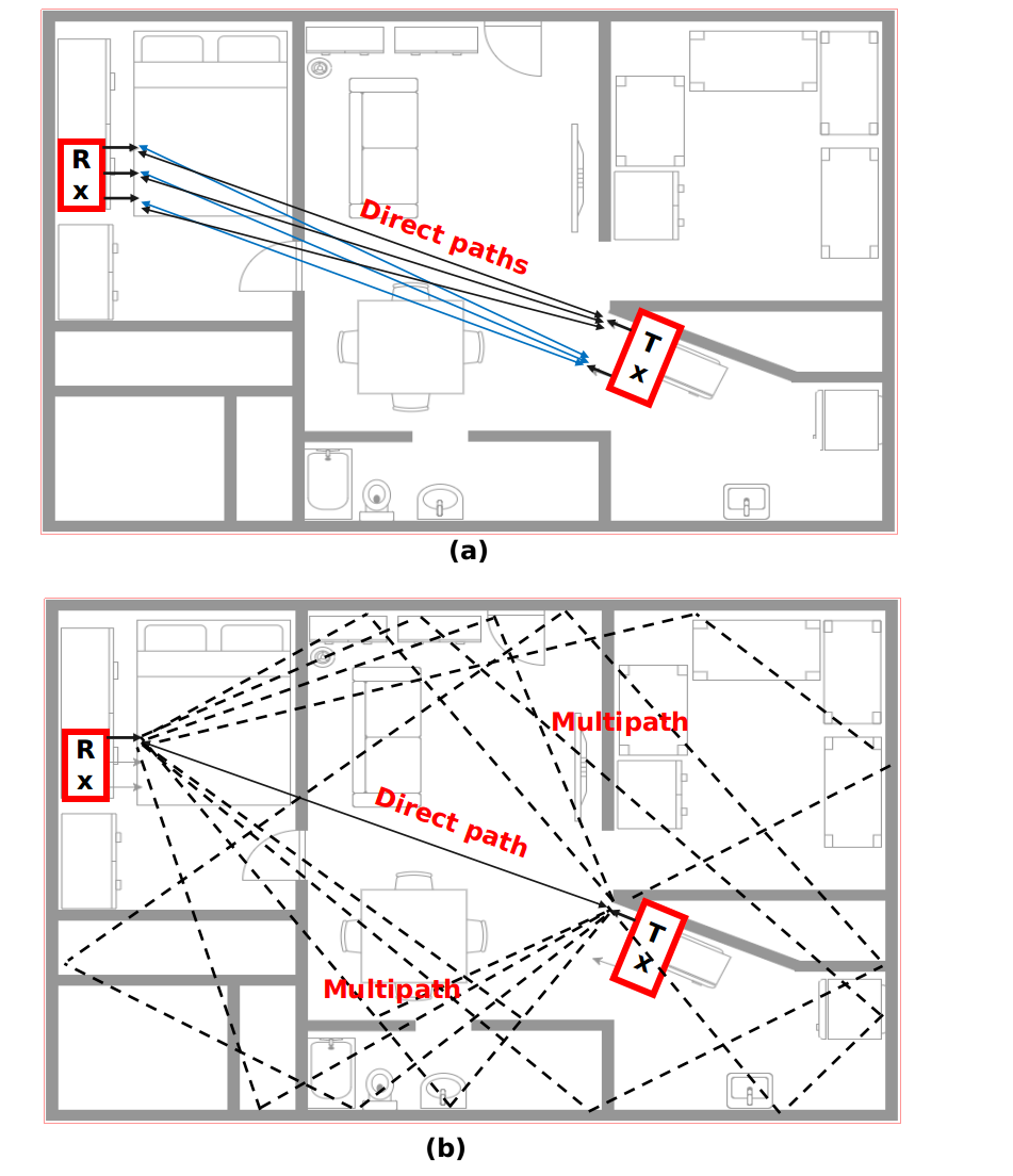
The sensing infrastructure is the WiFi infrastructure that is already deployed in any home or business space.Before analyzing any particular WiFi device or network topology, Figure 1 illustrates the propagation mechanism of indoor WiFi signals. Suppose there is a WiFi transmitter and a receiver both with multiple antennas as in Figure 1. The communication system will exhibit a direct path between each transmitter antenna and each receiver antenna as illustrated in Figure 1(a). In addition to the direct path, there are also multipath components associated with each of the direct paths which generates a fine-grained grid of signals travelling along the space as shown in 1(b). A human being, a pet, or any object moving within the space illustrated in Figure 1 will distort the signals that are travelling be-tween transmitter and receiver. This fine-grained grid is described by the measurements that characterize the wireless channel. In the physical layer description of standards like IEEE 802.11n (WiFi 4), IEEE 802.11ac(WiFi 5), or IEEE 802.11ax (WiFi 6) these measurements are registered as CSI.
2.1 Brief description of CSI
The mechanism of collecting CSI measurements between two WiFi devices, e.g. a Google mini connected to an access point (AP), can be summarized in a simple way, ignoring additive noise and/or interference, through the following equation in frequency domain:
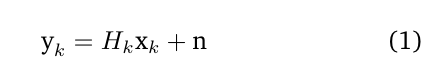
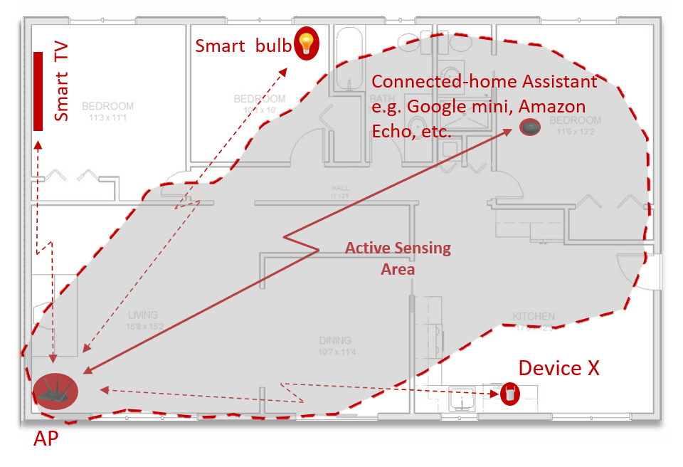
where, Hk is the wireless channel matrix established be-tween the AP and the Google Home Mini as illustrated in Figure 2 with dimensionsNRXxNT X. The number of receiving and transmitter antennas are NRX and NT X, respectively. xk represents the sounding signal and yk is the received signal. The baseband equivalent channel Hk is a complex value and the wireless channel affects the phase and amplitude of the transmitted signals. The estimation of Hk is the under going measurement behind the CSI reports that are later ex-changed between WiFi devices. In other words, CSI is no more than a report that describes the relationship between a signal that a transmitter is sending, xk, and the signal received on the other end of the wireless link, i.e.yk. The exact relationship can be established because of the knowledge that the receiver device has about the training sequence emitted on the transmitter side. That relationship has different dimensions. One dimension is the number of spatial streams. The spatial streams can be seen as using parallel channels the signal could take to reach the receiver. A single stream is formed between each pair of transmitter and receiver antennas. This is an important concept from multiple-input multiple-output (MIMO) systems which is what the standards are based on. CSI reflects the behavior of those different spatial streams and, in general, the behaviour of the wireless channel.
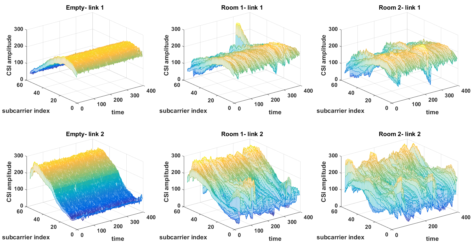
In order to visualize the concept explained above, Figure 3 shows an example of the amplitude of CSI for a wireless link established between two different WiFi devices. Figure 3 shows the amplitude of two channel coefficients versus subcarriers plotted over multiple frames (along rows) and three different tests (along columns). In the first test the CSI information is collected when no one is within the sensing area, i.e. an empty dwelling. The second test (second column) was recorded when a person was continuously walking in a room i.e. Room 1. In the third test (along the third column), the person was walking in a different room of the dwelling labelled as Room 2. For the three tests, two out of the sixteen available spatial streams are represented along the rows of figures in Figure 3
2.2 A Star Topology
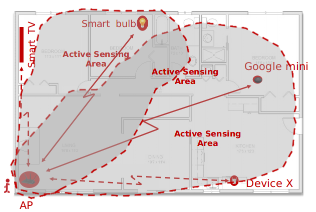
In a typical WiFi deployment there are different types of network topologies that can be used. As illustrated in Figure 2, a sensing area is generated through at least two connected devices, for example, it could be the AP and the Google mini. Figure 4 shows the same space, although in this case two of the clients or station devices have been used to generate the sensing area created by the union of the areas that each of them cover. In this case, Aerial collects CSI measurements in the AP by using a small software agent with negligible footprint in the AP. The overall architecture of the solution is further discussed in Section 3.This example illustrates the ability of collecting CSI in a residential router by using available clients like a smart bulb and the Google mini. The WiFi network topology represented in Figures 2 and 4 is known asa star topology. Aerial can leverage this topology to generate multiple sensing areas.
The boundaries of the sensing area may not be clearly defined. In most cases, the specific shape of the sensing area is unknown since it will depend on the environ-ment (type of house, size, number and type of walls, etc.), the specific communication system generating the sensing area (hardware), the power levels employed by the devices involved and the distance between them.
2.3 Extended Star Topology
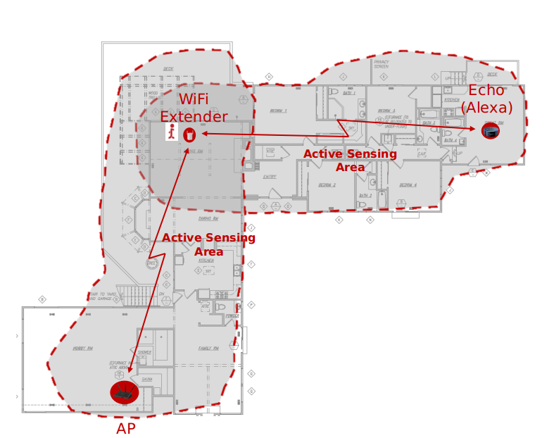
If there is any repeater in the WLAN, and the CSI in-formation is collected in that repeater, there could be a sensing area generated by the connection between the repeater and the router that the repeater is associated with. Another sensing area could be generated between the repeater and any other WiFi Client connected to that repeater, as shown in Appendix A Figure8. At the same time, the router that is also an AP, can be connected to other client stations generating other sensing areas. For multiple ISPs and WiFi vendors, this is the preferred option. In this way, a WiFi repeater can increase the WiFi coverage for larger houses. It is usually required in houses with more than1,500s.f. In this case, the AP or home router usually has a minimum of three to four antennas
2.4 Mesh Topology
Another deployment option often employed by ISPs and WiFi manufacturers is a mesh topology. In this topology, there are multiple APs involved where a mini-mum of two is required. Those APs are usually referred to as Mesh APs. The amendment to the IEEE 802.11standard to include mesh is 802.11s (802.11s, 2011).This topology splits the traffic load of the AP of a star topology deployment by deploying multiple APs. Each client can associate with the closest AP or, depending on the management software of the mesh, with an AP that is not the closest but has less traffic load and it is within a good coverage range. Usually, the wireless linke stablished between WiFi Clients and APs are stronger due to the presence of multiple APs. However, there is a logic (commonly translated into an additional software layer) behind this topology since there is traffic that needs to be circulated between the different APs in charge of transporting user data to the Internet.
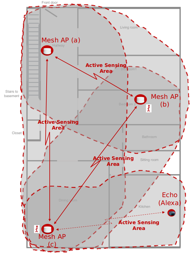
Mesh is another topology that Aerial leverages to deploy human activity classification. As an example, the sensing areas generated by this topology can look like the one in Appendix A Figure 9. Notice that with only two devices where Aerial’s agent is installed on, four different sensing areas are generated by leveraging the existing devices in the network. There are three sensing areas generated by the APs composing the WiFi mesh network, and one sensing area generated by one of the STA devices that is connected to the closest AP mesh node.
Aerial support all the above-mentioned WiFi topologies which provides a wide flexibility for deployingWiFi sensing services independently of the particular topology deployed by the customers.
3 Case Study: Human Motion Detection
Now let’s see how this theory works in practice. FromApril 1st 2019 to July 31st 2019, Telefónica and AerialTechnologies conducted a Pre-commercial pilot with aPeace of Mind application. The Aerial software Agent was remotely installed on the Telefónica FTTH Router of those Telefónica users that participated in the pi-lot. The CSI information was extracted from the FTTHRouter, specifically from a ON Semiconductor Quantenna 4x4 chipset in the 5.1 GHz frequency band. In this particular study, an inexpensive 1x1 plug-in WiFiClient was provided to the users of the pilot to allow them to easily control the Detection Area.
The CSI data was encrypted and sent it to a cloud service where the algorithms were running. It is im-portant to mention that raw CSI measurements do not contain any information understandable by a human being and it is independent of the data content of the frames. Please refer to Figure 3. When human, objects, or pets move through the indoor environment, they create disturbances which are reflected in the collectedCSI information. Aerial developed the ability to recognize patterns to detect human motion (avoiding pets),human presence, and other product features by analyzing WiFi signal disruptions through Machine Learning techniques.
One of the primary capabilities of Aerial technology is the motion modelling algorithm that is able to:
- Quantify WiFi disturbances caused by human motion and micro-motion within a sensing area into a numeric activity level.
- Determine occupancy status of a sensing area based on the activity level; empty or occupied.
- Determine the moving status of a person within an occupied sensing area based on the activity level; active (motion) or static (presence).

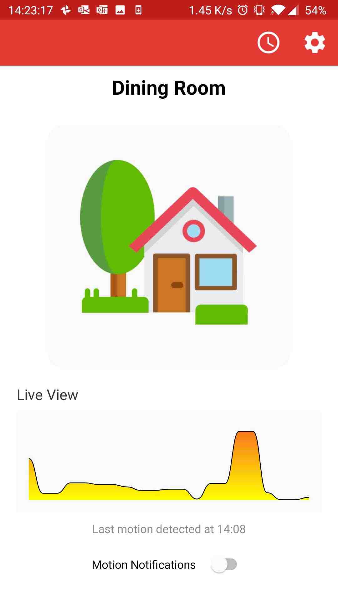
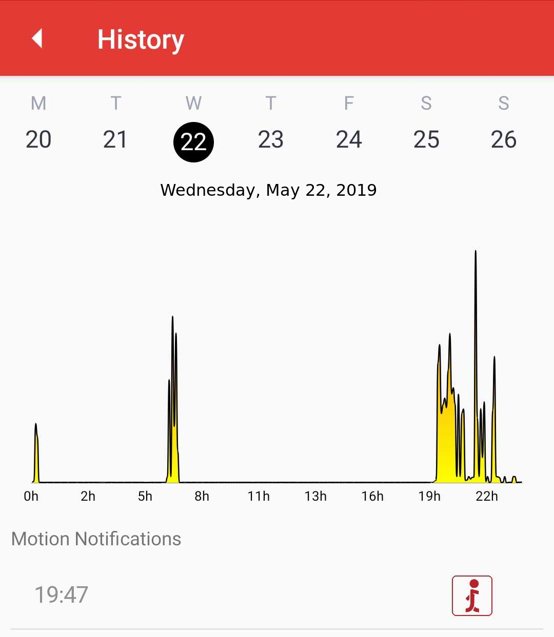
A screenshot of the application is displayed in Figure 5 showing a notification of Motion Detected in theHome being sent to the user. The users were then able to acknowledge the notification as expected motion and report unexpected events. The users were also able to see a real-time stream of Motion activity from someone walking in their home as shown in Figure 6.In Figure 7, the history of motion activity in a home on a typical work day was captured. The user wentt o bed after midnight, prepared for work around 7:00and arrived home at 19:47 where a motion notification was received by the user.
Throughout the entire Pre-commercial pilot duration, users demonstrated a level of engagement 2X higher than that observed with their existing Smart WiFi application. Furthermore, the pilot exposed insightful information. Such as:
- A total of 14,457Motion Detection Notifications were sent during this pilot (when enabled by the user). Less than 0.05% of Motion Detection Events were reported as Unexpected.
- The majority (80%) of app users used the MotionHistory to go back in time to know when Motion events occurred in their space. Figure 7 shows an example of the Motion History screen.
- None of the users reported a True Negative (TN)event, i.e. entering the home and not being notified.
4 Conclusions
This case study explains the fundamental concepts behind the technology developed at Aerial Technologies and how it was deployed in Telefónica's Pre-commercial pilot. A good understanding of the ba-sic concepts exposed in this paper is key in order to show the value which can be created for Telefónica’s clientele.
The pilot proved that Aerial is an enabler for many value added services that can leverage Motion intelligence. This pilot focused on Peace of Mind and Intrusion detection, but this is just the tip of the iceberg. This technology has applications in Smart Home Automation, Security, Remote care, Hospitality, Enterprise and more, with more advanced motion services such asPresence, Sleep monitoring, Location, Fall detection and more. WiFi Motion Intelligence is set to become a corner stone enabling technology for the Smart Home and Smart Building ecosystem.
Bibliography
Michel Allegue1, Negar Ghourchian1, Mathieu Rozon1, Emilie Carignan1, Mark Hopper1, Juan Felipe Gonzalez1, Sam Heidari1, Carlos Gandarillas2, Rubens Cesar2, Jose Aranda2, Jose Luis Espla2, Zahira Almazan2, Joant Domınguez2, Oscar Mancebo2, Oscar Sol ́a2, Jos ́e Manuel Nistal2, Marıa Angeles Barba2, Mar ́ıa Jos ́e Ginel2, Guenia Gawendo2, Barbara Albizuri Richter2
1 Aerial Technologies Inc. - Montreal, QC
2 Telef ́onica, - Madrid, Spain
802.11, IEEE (2016). “IEEE Standard for Information technology–Telecommunications and information ex-change between systems Local and metropolitan area networks–Specific requirements - Part 11: Wire-less LAN Medium Access Control (MAC) and Physical Layer (PHY) Specifications”. In:IEEE Std 802.11-2016 (Revision of IEEE Std 802.11-2012), pp. 1–3534.doi:10.1109/IEEESTD.2016.7786995
802.11ac, IEEE (2013). “IEEE Standard for Information technology– Telecommunications and informa-tion exchange between systems Local and metropolitan area networks– Specific requirements–Part 11:Wireless LAN Medium Access Control (MAC) and Physical Layer (PHY) Specifications–Amendment 4:Enhancements for Very High Throughput for Operation in Bands below 6 GHz.” In:IEEE Std 802.11ac-2013, pp. 1–425.doi:10.1109/IEEESTD.2013.6687187
802.11n, IEEE (2009). “IEEE Standard for Infor-mation technology– Local and metropolitan areanetworks– Specific requirements– Part 11: WirelessLAN Medium Access Control (MAC)and PhysicalLayer (PHY) Specifications Amendment 5: Enhance-ments for Higher Throughput”. In:IEEE Std 802.11n-2009, pp. 1–565.doi:10.1109/IEEESTD.2009.5307322
802.11s, IEEE (2011). “IEEE Standard for InformationTechnology–Telecommunications and informationexchange between systems–Local and metropolitanarea networks–Specific requirements Part 11: Wire-less LAN Medium Access Control (MAC) and Physi-cal Layer (PHY) specifications Amendment 10: MeshNetworking”. In:IEEE Std 802.11s-2011, pp. 1–372.doi:10.1109/IEEESTD.2011.6018236.
Chen, X. et al. (2017). “Taming the inconsistency ofWi-Fi fingerprints for device-free passive indoor lo-calization”. In: pp. 1–9.doi:10.1109/INFOCOM.2017.8057185.
Dash, Debashis and Abhishek Agrawal (2019). “En-abling CSI-based motion detection in existing Wi-Finetworks”. In:IEEE Global Communications Confer-ence (Globecom 2019).
Ghourchian, Negar and Michel Allegue-Martinez(2017). “Modeling multi-layered behavior of elderlypeople in smart homes”. In:Women in Machine Learn-ing Workshop (WiML 2017)
Ghourchian, Negar, Michel Allegue-Martinez, andDoina Precup (2017). “Real-Time Indoor Localiza-tion in Smart Homes using Semi-Supervised Learn-ing”. In:Proceedings of the 29th AAAI Conference onInnovative Applications (IAAI-17), pp. 4670–4677
Samadh, Abdul et al. (2019). “Indoor Localizationbased on Channel State Information Learning”. In:IEEE Topical Conference on Wireless Sensors and Sen-sor Networks (WiSNet2019).
Appendix A
Remote Care pilot makes Spanish TV News
2021/08/30
Ambient Remote Care Offerings Are a Win-Win for ISPs, Seniors, and Caregivers - Health Insight
2021/06/07
WiFi Sensing for Senior Independence
2020/11/23